Alarm system RASPBERRY PI, ARDUINO and LoRa RF1276D27
Release time:2019-12-02
General Description
This is an alarm system based on a Rapberry Pi acting as alarm center and one or more Arduinos as remote stations. Remote stations communicate with the alarm center through RF1276D27 module.
The control panel has the function of periodic consultation (every 10 seconds) of each stations to detect their status and a possible deactivation of communications by some type of inhibitor frequency or power failure.
The central implemented in a Raspberry Pi, is connected by wi-fi. It communicates by email the trigger of some of the stations as well as any communication failure with any of the stations.
Also, periodically (every hour) an email is sent to the administrator reporting the status of the stations.
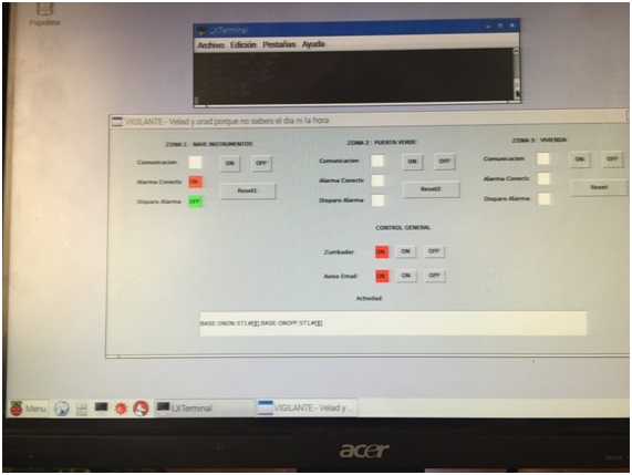
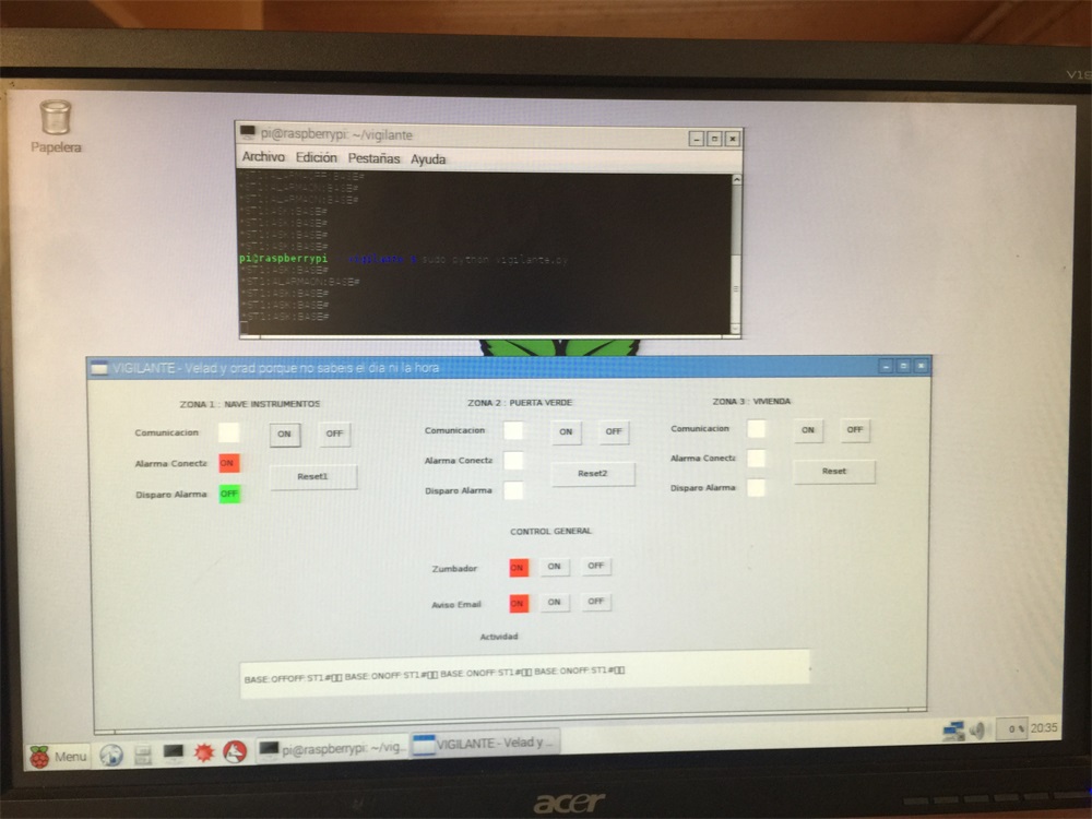
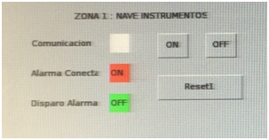
Control screen Alarm Central by a python program running on the Raspberry Pi:
Station 1 ( ST1 ): Arduino
Each station is identified by a number. Station 1 is identified with ST1. As explained in this section is equally valid for the following station, ST2, ST3 ... STN
Each of the stations can be implemented by an Arduino and a RF1276D27 module. Arduino is basically checking:
a) The state of the PIR shot ( triggered pin )
b) The status of the pin connected Alarm
c) The status of the pin Alarm off.
d) The control unit communicates with each of the stations using commands. The structure of a command is:
DESTINATION:COMMAND:ORIGIN#. For example, the command ST1:ASK:BASE# indicates:
DESTINATION = ST1 (the command is addressed to the ST1 will be the only one that will response the command)
COMMAND = ASK (Command status query)
ORIGIN = BASE (Base is the alarm center is the source of the query) Station 1 BASE bound respond with their status, for example BASE:ONOFF:ST1#.
Central Alarm commands can be:
ST1:ASK:BASE# As I explained earlier, this is the query command that sends the plant to each station. Before this command, the station responds with BASE:XXYY:ST1# where XX indicates the ON / OFF status of the station (ST1) and where YY indicates the ON / OFF trigger station (ST1). Example BASE:ONOFF:ST1# indicates that the alarm is connected but no triggered.
ST1:ALARMARESET:BASE# Reset command. Puts station 1 (ST1) in disconnected state and no triggered.
ST1:ALARMAOFF:BASE# Command to deactivate the station 1 (ST1).
ST1:ALARMAON:BASE# Command to activate the station 1 (ST1).
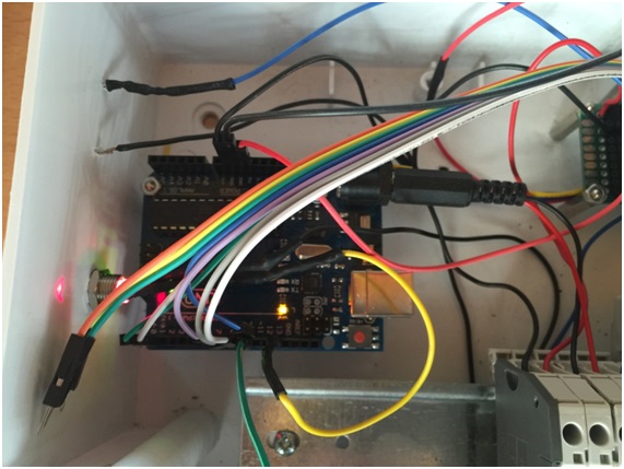
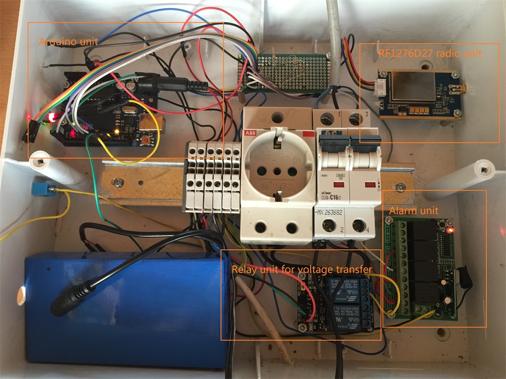
In the prototype example, station 1 (ST1) is composed of:
• Arduino Uno or compatible: It is powered by 12V battery and through its 5V output, the RF1276D27 module is supplied.
The Arduino response the commands it receives from the alarm center via the RF1276D27. Also check the status of the PIR shot by one of its pins.
In two other pins checks whether the alarm is switched on or off by remote control.The remote control use the A channel to activate the alarm and the B channel to disactivate the alarm.
http://www.banggood.com/UNO-R3-ATmega328P-Development-Board-For-Arduino-No-Cable-p-964163.html
· Siren Alarm: It is connected with Arduino via an output pin and a relay interface to provide the 12 volt alarm power supply.
http://www.banggood.com/12-Volt-Security-Systems-Alarm-Strobe-Light-Siren-p-914565.html
· Remote Control: This remote control is used for connection or disconnection of the alarm.
http://www.banggood.com/12V-4CH-Channel-315Mhz-Wireless-Remote-Control-Switch-p-960985.html
· Relay Interface: The interface relays allows us to change the output signals level of Arduino from 5V to 12V needed by the siren to sound.
http://www.banggood.com/5Pcs-2-Way-Relay-Module-With-Optocoupler-Protection-p-975776.html
· RF1276D27 Module: This module connects directly to the Arduino without any interface. It is connected with the outputs pin of Arduino 0V(GND). and 5V. and communicates through the TX and RX pins of Arduino.
https://www.appconwireless.com/showpro.php?id=84
|
Arduino |
RF1276D27 |
|
GND |
GND |
|
5V |
5V |
|
TX |
RX |
|
RX |
TX |
· 12V
Battery: The battery is kept charged by a transformer from 220V to 12V. The
battery output is connected directly to the power in connection on the Arduino
board.
· PIR Sensor: Motion Sensor commercial use.
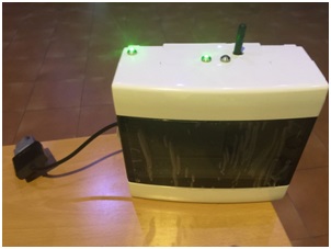
· Buzzer: To indicate the status enabled or disabled of alarm.
Station 1 image:
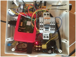
Alarm Center (BASE): Raspberry Pi
The alarm center is identified in the system as BASE. Therefore each command is sent with field ORIGIN = BASE and receive commands have field DESTINATION=BASE.
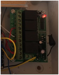
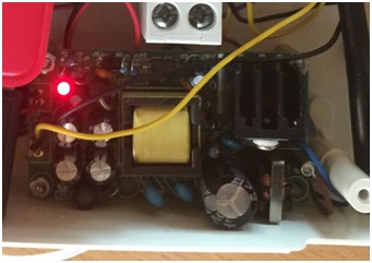
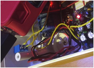
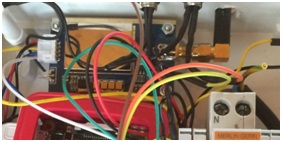
Prototype images:
Basically the Raspberry check periodically the status of each one station by commands like STN:ASK:BASE# (where N is the number of station on request).When it receive the status, it shows on the application screen control. Also communicates the status of stations with administrator by email.
In case of alarm triggered, administrator is advised immediately. In case of normal status (no triggered) an email is sent every hour to report. If any station does not respond to commands ASK, it is similar to the trigger of the station, as it is interpreted that the station could be off by some frequency inhibitor.
Also from the control panel, you can reset, activate or deactivate alarms by the corresponding buttons on each station.
Also generally you can disable the siren and sending email using a button for this purpose:
In the prototype example, the control unit (BASE) is formed by:
· Raspberry Pi: is powered by the 5V power source in the following image. This source also provides 12 V for the alarm siren:
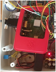
The Raspberry Pi is equipped with four USBs. I used for a wi-fi adapter, a wireless mouse and keyboard. The connection to the video monitor is made using the built-in HDMI connection Raspberry.
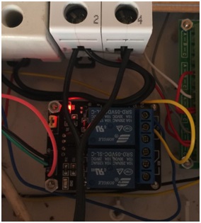
• Relay Interface: The interface relays allows us to change the output signals of the Raspberry 3V to 12V signals needed by the alarm siren to sound.
http://www.banggood.com/5Pcs-2-Way-Relay-Module-With-Optocoupler-Protection-p-975776.html
· Alarm Siren: Connects to the Raspberry through an output pin and relay interface to provide the 12 volt alarm.
http://www.banggood.com/12-Volt-Security-Systems-Alarm-Strobe-Light-Siren-p-914565.html
· RF1276D27 Module: This module connects directly to the Raspberry without any interface. It is powered with the outputs of 0V ( GND) and 5V. of Raspberry Pi and communicates through the TX and RX of the Raspberry pins.
|
Raspberry |
RF1276D27 |
|
GND |
GND |
|
5V |
5V |
|
TX |
RX |
|
RX |
TX |
https://www.appconwireless.com/showpro.php?id=84
• Buzzer and LEDs: To indicate that status (enabled or disabled ) alarm in any station.
Basically the functions of the Central Alarm are:
a) Every 10 seconds is checked each stations through ASK commands (for example ST1:ASK:BASE#) through RF1276D27 module.
If the answer to any station is “triggered alarm” or “no response” at a scheduled time after several attempts, the central siren will be activated and sent a email warning to the administrator from Raspberry. Both the siren alarm and email can be disabled from the application screen using the corresponding buttons.
b) Every 2 seconds serial communications are read to check the responses from each station. The status of each station is reflected in the control screen with status lights in green or red colour.
c) Also it is reflected on the screen any communications activity received in the RF1276D27
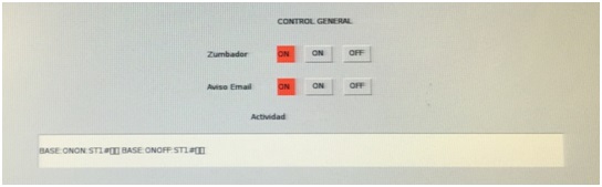
module.
d) Each hour, an email is sent to the administrator with the state of the stations.
The Alarm Central software is done in Python and you can run a test version directly on a Windows PC with Microsoft Visual Studio:
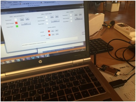
In this case, we can connect the RF module 1276 via a USB adapter and PL2303:
https://www.appconwireless.com/showpro.php?id=121
